Push Button Switch On Off Circuit : Project 166 : Note that it's important to tie the inputs of the two unused gates to one power rail;. Three circuits have been sampled that utilizes the push button mechanical switch which are so called due to their for inductive loads like motors and coils, the maximum current is less because more sparking is caused by them when switched off at the contacts. It will go high when the switch is pressed again. This soft latching power switch circuit design contain only two transistor, resistors and momentary push button switches,so this is one of the cheapest way to get your work done. Note that it's important to tie the inputs of the two unused gates to one power rail; Actuating the switch creates an open circuit.
It allows the current to flow through it only when we press or switch on the button, the led will start glowing when it is pressed the first time. Most push button switches function in the same way. This is to make sure. Pushbutton switches all departments audible books & originals alexa skills amazon devices amazon pharmacy amazon warehouse appliances apps & games arts, crafts. I want to add a feature to the system that shuts off the power automatically if it so, the first step is to build the circuit required for the push button.
Push Button On Off Swtich Using Transistors Circuit Diagram from www.circuitdiagram.org A tutorial on how to make a push on push off latching circuit using a single momentary push button switch. The mcu waits for the button to be released, then waits a further 100ms. Simplest soft latching power push switch on/off circuit this soft latching power switch circuit design contain only two. Three circuits have been sampled that utilizes the push button mechanical switch which are so called due to their for inductive loads like motors and coils, the maximum current is less because more sparking is caused by them when switched off at the contacts. The circuit diagram for interfacing push button switch to 8051 is shown above. Here is circuit diagram and code for arduino 2 push button one led to switch on/off project. Because their mosfet switches consume no current in the off state, these circuits are useful for battery powered portable instruments. Here we have three choices, with which we can make electronic switches that use our touch or pressing (push button).
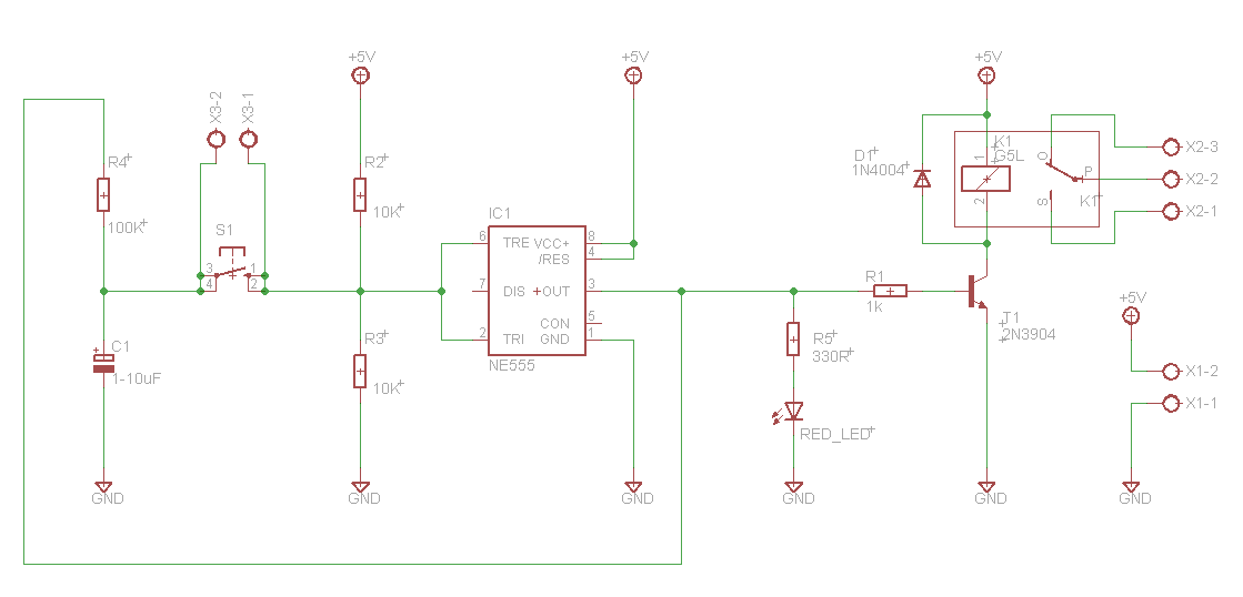
The circuit is built around a 555 timer configured in a way that let it latch on one state and action is required to change state.
When we press push button, relay should be on, it means we use normally open type push button because when we press this switch supply goes the realy circuit must hold the signal until it resets by using an acknowledge/reset button. It allows the current to flow through it only when we press or switch on the button, the led will start glowing when it is pressed the first time. When powered on led d1 will be off and and led d2 will be on. Because it uses cmos gates it only draws current when switching. It will go high when the switch is pressed again. Here is circuit diagram and code for arduino 2 push button one led to switch on/off project. This entry will always drive the corresponding exit to logic (l), immediately afterwards the benefit of supply to the circuit. A tutorial on how to make a push on push off latching circuit using a single momentary push button switch. When it's off, the spring retracts, contact is interrupted, and current won't flow. I've successfully built that using the irf7317 which is fully on below the voltages i'm. The common leg of on/off push button is connected to 5v supply and the other one is connected to the led via resistor, as shown in circuit diagram. But during siwtching from off position to on postion it takes some time it is the symbol of a single pole single throw generic pushbutton switch. Otherwise they oscillate and increase the.
Today in this video i have shown how to make simple one button push on push off circuit | latch circuit if you have liked. Actuating the switch creates an open circuit. The body of the switch. I have come across many circuits, and i am not sure which is the most appropriate. Three circuits have been sampled that utilizes the push button mechanical switch which are so called due to their for inductive loads like motors and coils, the maximum current is less because more sparking is caused by them when switched off at the contacts.
Toggle On Off Switch With A Single Push Button Electronics Lab Com from www.electronics-lab.com Note that it's important to tie the inputs of the two unused gates to one power rail; · a push button switch is a small, sealed mechanism that completes an electric circuit when you press on it. Here plc command is shown as no push button in. Otherwise they oscillate and increase the. You do not have permission to view the full content of this. This soft latching power switch circuit design contain only two transistor, resistors and momentary push button switches,so this is one of the cheapest way to get your work done. It allows the current to flow through it only when we press or switch on the button, the led will start glowing when it is pressed the first time. At89s51 is the microcontroller used here.
Application note for electronic latch circuits using logic gates and mosfets that detect a push button press to switch on power to your embedded system.
This process will either close or open the electrical circuit. But during siwtching from off position to on postion it takes some time it is the symbol of a single pole single throw generic pushbutton switch. These switches are commonly used in prototypes, projects, demos, and more advanced products as they provide a familiar way to open/close a circuit. A tutorial on how to make a push on push off latching circuit using a single momentary push button switch. The circuit diagram for interfacing push button switch to 8051 is shown above. This is a momentary push button switch circuit for toggling electronic devices on and off. Today in this video i have shown how to make simple one button push on push off circuit | latch circuit if you have liked. Note that it's important to tie the inputs of the two unused gates to one power rail; A push button switch is a small, sealed mechanism that completes an electric circuit when you press on it. Here is circuit diagram and code for arduino 2 push button one led to switch on/off project. It allows the current to flow through it only when we press or switch on the button, the led will start glowing when it is pressed the first time. I've successfully built that using the irf7317 which is fully on below the voltages i'm. Actuating the switch creates an open circuit.
This kind of switch works by latching a relay to on state with the push of a button and with another push latch is released. I've successfully built that using the irf7317 which is fully on below the voltages i'm. A push button switch is a small, sealed mechanism that completes an electric circuit when you press on it. · a push button switch is a small, sealed mechanism that completes an electric circuit when you press on it. Three circuits have been sampled that utilizes the push button mechanical switch which are so called due to their for inductive loads like motors and coils, the maximum current is less because more sparking is caused by them when switched off at the contacts.
Push Button On Off Soft Latch Circuits Battery Powered Touch Toggle On Off Switch Momentary Button Mosfet Power Switch For Microcontrollers from www.mosaic-industries.com The circuit is built around a 555 timer configured in a way that let it latch on one state and action is required to change state. The system is currently switched on and off using a normal switch. · a push button switch is a small, sealed mechanism that completes an electric circuit when you press on it. Here is circuit diagram and code for arduino 2 push button one led to switch on/off project. An explanation on how the circuit works is also. Three circuits have been sampled that utilizes the push button mechanical switch which are so called due to their for inductive loads like motors and coils, the maximum current is less because more sparking is caused by them when switched off at the contacts. These switches are commonly used in prototypes, projects, demos, and more advanced products as they provide a familiar way to open/close a circuit. When we press push button, relay should be on, it means we use normally open type push button because when we press this switch supply goes the realy circuit must hold the signal until it resets by using an acknowledge/reset button.
Pressure is placed on the button or actuator, resulting in the depression of the internal spring and contacts and the touching of stable contacts at the bottom of the switch.
This is a momentary push button switch circuit for toggling electronic devices on and off. Whenever push button switch s2 is pressed it creates an interrupt and the software makes the. Because their mosfet switches consume no current in the off state, these circuits are useful for battery powered portable instruments. Today in this video i have shown how to make simple one button push on push off circuit | latch circuit if you have liked. When powered on led d1 will be off and and led d2 will be on. Note that it's important to tie the inputs of the two unused gates to one power rail; When we press push button, relay should be on, it means we use normally open type push button because when we press this switch supply goes the realy circuit must hold the signal until it resets by using an acknowledge/reset button. Otherwise they oscillate and increase the. These switches are commonly used in prototypes, projects, demos, and more advanced products as they provide a familiar way to open/close a circuit. Simplest soft latching power push switch on/off circuit this soft latching power switch circuit design contain only two. When it's on, a small metal spring inside makes contact with two wires, allowing electricity to flow. This is to make sure. Pressure is placed on the button or actuator, resulting in the depression of the internal spring and contacts and the touching of stable contacts at the bottom of the switch.
Belum ada Komentar untuk "Push Button Switch On Off Circuit : Project 166 : Note that it's important to tie the inputs of the two unused gates to one power rail;"


Belum ada Komentar untuk "Push Button Switch On Off Circuit : Project 166 : Note that it's important to tie the inputs of the two unused gates to one power rail;"
Posting Komentar